4. Large setups and optimization
Getting a single radio mic to work is usually no major challenge. Things get more interesting when you have to deal with interfering factors, or if you want to run several radio mics simultaneously. This chapter will deal with how you can get a better result in your purchasing decision and in your operation, and with what you should bear in mind running several systems.
Important features
By choosing the right radio system and features you can already pave the way towards a reliable radio setup. Switchable frequencies are worth their weight in gold whenever interference occurs on your chosen frequency. The number of switchable frequencies itself is less important; you'll just be glad you can switch if the need arises.
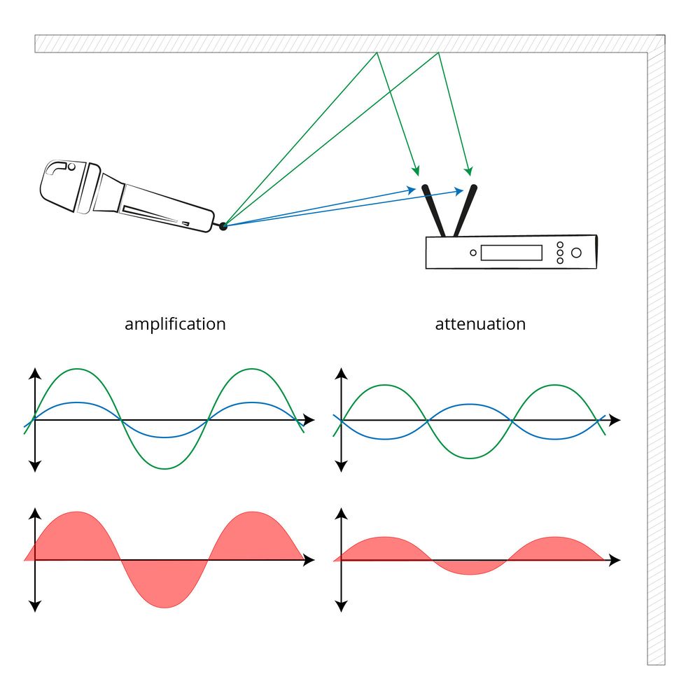
Another feature you should pay attention to is diversity reception, apparent from double antennae. The main difference here is between antenna diversity and the slightly better true diversity with two separate receivers. There are differences, but they do not matter much in practice. Diversity or no diversity, that is the key question. Diversity reception plays a key part in avoiding dropouts which are caused by reflections in the room.

Safeguarded reception through diversity
The signal's detour via walls, ceilings and floors causes interferences in the radio signal at the receiver end. Sometimes the reflections add to the direct signal (good), but sometimes they attenuate each other (bad). In the worst case this may even lead to brief dropouts. Whenever the transmitter is in motion in particular, geometric conditions constantly change. A second antenna positioned elsewhere in the room ensures that the dropout practically does not occur at both antennae simultaneously. Diversity receivers are therefore backup receivers.
A greater output power may be an advantage if the signal needs to cross longer distances. Entry-level setups usually feature 10 mW, professional setups usually offer switchable output power up to 50 mW, which will add a few metres depending on other factors as well. With shorter distances, greater output power is actually disadvantageous, and it'll also empty your batteries sooner. As usual, the rule is: as rarely as possible, as often as necessary.
Distribution over frequency ranges
Depending on the extent of your setup, it may make sense to distribute the systems over various frequency ranges intuitively instead of cramming them all into one narrow frequency band. It is advisable to always remain below the maximum recommended number in order not to take the system to its limit of instability and to have some backup channels available in case of interference. Additionally, it is a good idea in fixed installation to investigate potential sources of interference on location. If InEar radio applications are also present, it makes sense to allocate a discrete frequency band to them and place the InEar transmitters a few metres away from the mic receivers.
Choosing your frequency methodically
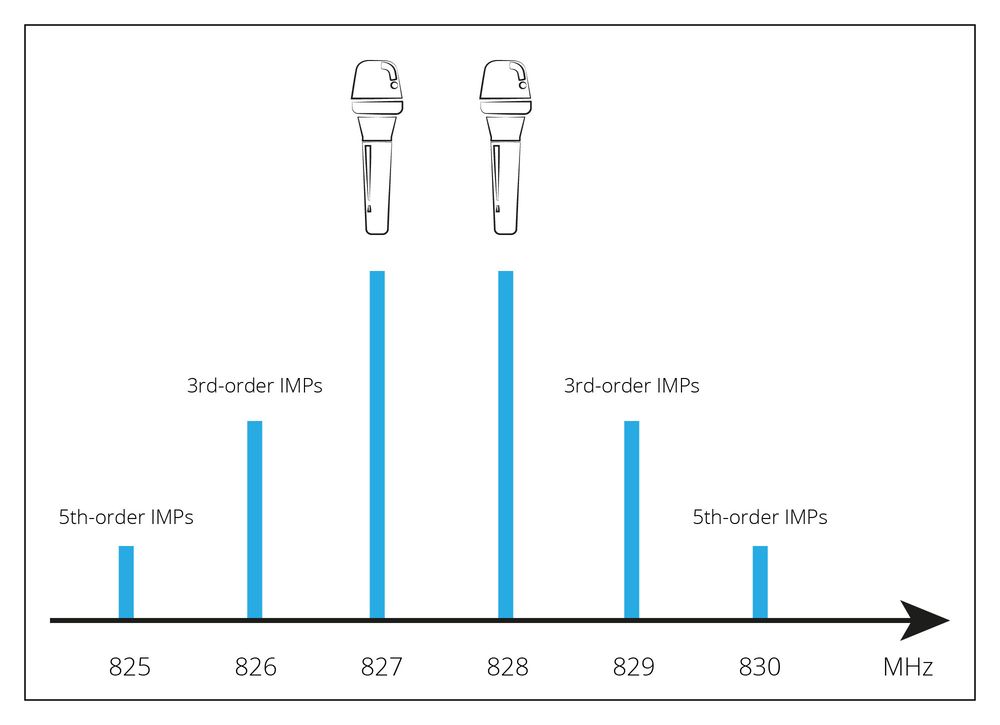
We should now be fully aware that if we operate several transmitters, we have set to difference frequencies. The necessary safety distance between two carrier frequencies is pretty low, by the way, at 400 kHz (0.4 MHz). The so-called intermodulation products are the real challenge here. Figuratively speaking, they are further frequencies that arise in the interaction between two transmitters.

Third-order intermoduilation products
There are many of these, but most of them are at large multiples of the frequency and do not interfere. The two third-order modulation products, however, present a problem. They are calculated using the formulae 2*f1-f2 and 2*f2-f1, which means that they are equidistant above and below the frequencies of two radio mics (see figure). They are a problem because they arise in relatively close proxomity to our carrier frequencies and are thus difficult to filter out, obstructing the space for further carrier frequencies. But it gets even worse. With every additional transmitter, the intermodulation products multiply, since they all interact with each other. While we are dealing with only two critical intermodulation products when two transmitters are involved, a third transmitter results in nine of them. Furthermore, the strength of the interference increases the closer the transmitters are to each other. In extreme cases, the lower-order intermodulation products can also increase.
You can imagine how confusing the situation becomes with a rising number of radio links. Choosing the carrier frequencies randomly will end in chaos sooner rather than later. Mental arithmetric will also not be an option for most of us. By the way, the worst thing you can do is to set all radio systems to equidistant frequencies, since this would make the carrier frequencies and intermodulations overlap 100%.
There's a simple solution: frequency tables. In higher-end systems, these are already integrated as groups and channels. The idea behind this is that each group (also called bank) comprises two compatible channels (=carrier frequencies). Therefore, you should always stay within this group and select channels exclusively form this group. This will be especially easy if you only use systems of the same type. If a third-party system is added, it makles sense to set this by hand to a frequency available in your group. If the third-party sytsem is not switchable, it makes sense to check whether its 3rd-order intermodulation products occur as a set frequency anywhere in one of the groups. Then, you can migrate your complete setup to this group.
Extract from a frequency table
| Channel | Bank 1 | Bank 2 | Bank 3 |
| 1 | 518.200 | 524.250 | 530.100 |
| 2 | 518.700 | 524.800 | 530.800 |
| 3 | 519.650 | 525.550 | 531.650 |
| 4 | 520.450 | 526.550 | 532.050 |
| 5 | 520.900 | 527.700 | 533.050 |
| 6 | 521.600 | 528.100 | 533.550 |
| 7 | 522.000 | 529.050 | 534.850 |
| 8 | 522.900 | 529.500 | 535.750 |
| 9 | 528.800 | 516.950 | 517.300 |
| 10 | 535.100 | 535.250 | 523.300 |
| 11 | 552.350 | 536.750 | 547.200 |
| 12 | 531.600 | 554.900 | 551.050 |
Some receivers can also scan the frequency band for available frequencies. This may be a quick fix if you temporarily join an existing and functioning setup. But if you want to start a complex setup from scratch, scanning is only useful if and when all systems work together in a network. Modern high-end radio systems support this. Otherwise, leading radio mic manufacturers also offer software to calculate ideal frequency patterns. This has become established practice in major events.
Neat and tidy: antenna splitters
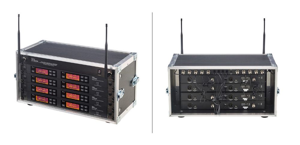
As the number of receivers rises, so does the number of antennae. Take a radio rack with eight diversity receivers: that would be 16 antennae in a very small space. Such a forest of antennae not only looks chaotic, the antennae also affect each other negatively. The antenna splitter's task is to reduce the number of antennae. Most often they also supply energy to the receivers, so that only one connection to the electricity outlet is necessary. Passive antenna splitters are available for two receivers, active ones mostly for four or more. Some splitters can also be cascaded, so that one of them manages all right antennae, the other all left antennae. With even larger setups you can use a master splitter to gather together several splitter radio groups in one device.

8-channel radio system with antenna splitter
If you have ever asked yourself why removable antennae are always positioned at the rear of the receiver, the antenna splitter gives you a good answer: optimization on the antenna side are only possible, of course, if there are removable antennae on the radio receiver. Entry-level systems with fixed antennae, or even antennae integrated into the casing, are not suitable for large-scale radio setups. Keep this in mind in your purchasing decision.
Antennae and antenna cables
Receiver antennae and their cables also offer potential for optimization. Systems usually come with short 1/4 lamba omnidirectional rod antennae. Emission occurs omnidirectional from the antenna axis. Rod antennae should not be pointed at the mic, since emission is weakest in the axial direction.
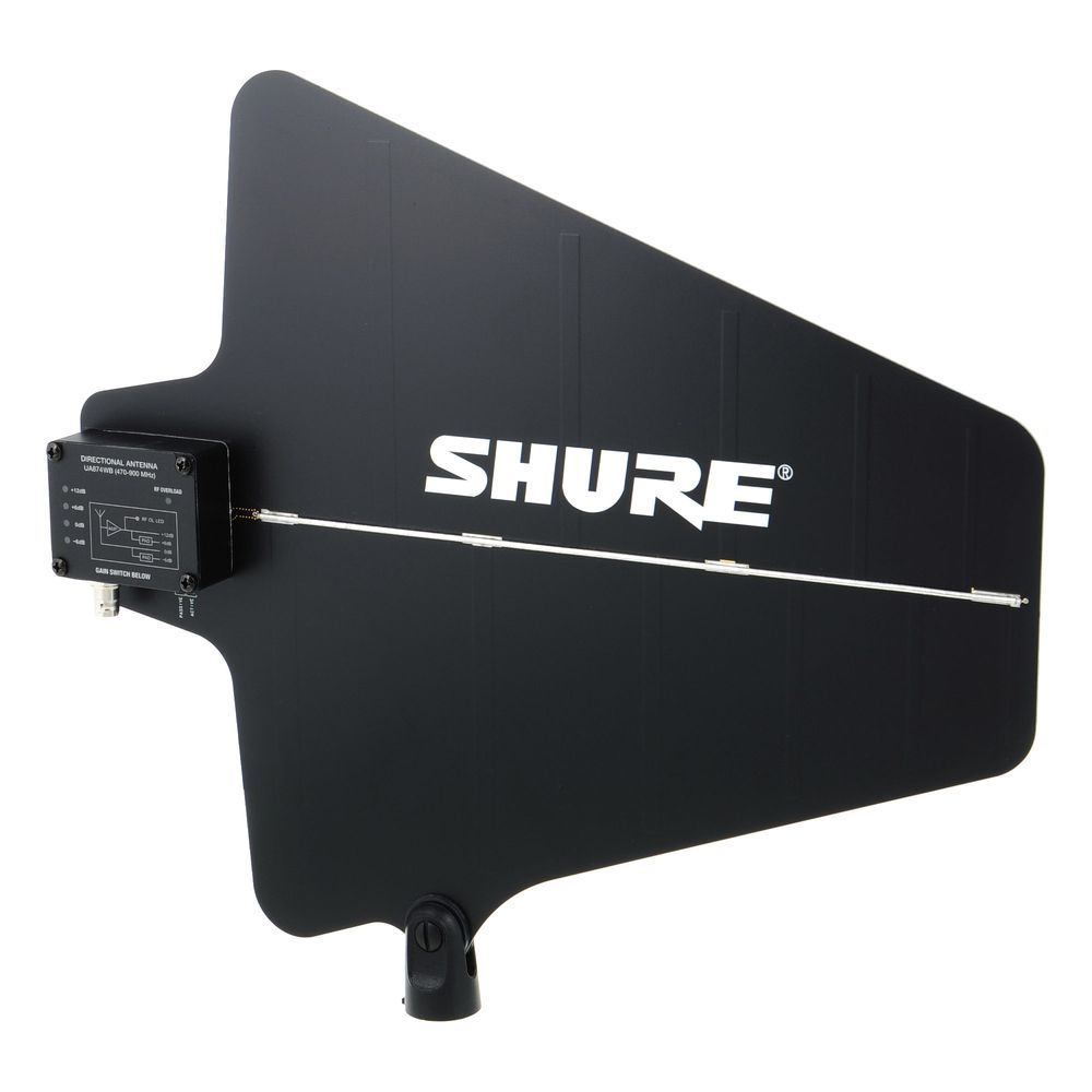
Directional antennae are a different matter. Emissions are directed in an arrow shape towards the radio mic/transmitter. Directional antennae offer better reception from a determined position, while interefering signals from outside the reception area are largely suppressed. You'll frequently see such directional antennae at events pointing across the stage from the sides. They are usually mounted on mic stands.

Directional antenna for stand mounting
In principle, remote antennae are always a good idea when the receiver rack is unfavourably placed. This is why omnidirectional antennae for rack mounting are also available. What is impportant is that the antenna must be intended for remote mounting, i.e. it mus have its own ground reference. The rod antennae the systems come with are usually not suitable for this use. They have to be mounted on the receiver or splitter, or have metal contact through the rack panel, respectively.
You need to chose your antenna cable carefully, since similar-looking cables, plugs, and connectors also exist for other applications with other characteristic impedance values. For radio systems we exclusively use components with 50 ohm. Antenna cables differ greatly regarding signal attenuation over distance. While optimum placement of the antenna has priority, you should still try to avoid using unnecessarily long cables. The longer the cable you need is, the better its quality should be, and you may need to use additional antenna amplifiers.For short cables, e.g. within the 19" unit, the cable quality is less important.
Receiver placement
Radio recveivers belong on the stage even and particularly if the mixing desk is at the other end of the hall. Please always keep in mind that a radio mic's primary purpose is allowing the performer freedom of movement rather than eliminating the cable connection to the mixing desk. While there should be a few metres' distance between the transmitter and the receiver, remember: the larger the distance, the weaker the incoming signal. In enclosed spaces, increased distance also leads to more reflections and interference which can further attenuate the signal. If at all possible, you should therefore avoid unnecessary distance and make sure that the sightline betwene transmitter and receiver is unobstructed. In places where you can absolutely not lay cables, good directional antennae may save you. They at least reduce lateral interference.
Good to know: attenuation and acoustic shadow
We'd like to mention here that radio waves can penetrate and/or circumnavigate objects, within limits. Glass, wood, and synthetic materials are usually easily penetrated. Bricks attenuate more strongly, reinforced concrete even more. Metal surfaces are the least penetrable, they are almost entirely reflective. Of course, the thickness of the material plays a part as well. The thicker the wall, the more the signal will be attenuated. Ideally, nothing but air should be between transmitter and receiver.
When we talk about people inbetween the transmitter and the receiver, the number is key. An audience of 500 between the two will attenuate the signal more than significantly. You should therefore not place the receiver at front of house. Conversely, individuals or similarly narrow objects, e.g. columns in a room, are almost entirely negligible. While any object between the transmitter and the revceiver casts something of a "radio shadow", their contours are not harshly delineated. The wavelenghts we are moving in are about comparable to sound waves.
An example may illustrate this: imagine your are sitting on a chair outside, and your favourite song is pouring from a speaker. The sound waves reach your year unimpeded. Now an inconsiderate and heavy-set person places themselves exactly between you and the speaker. This may not be the polite thing to do, but the sound waves will get to your ear even without sight contact. A trained ear would probably notice some slight attenuation in the highs. If ten more people join our "friend", you'd definitely notice the signal becoming weaker. The highs would become less clear, and mids would also suffer some attenuation. Basses will remain pretty much unaffected, though. With radio, things are quite similar. Smaller objects only rarely affect transmission. Medium-sized objects, however, may cause some negative effects on the radio path in the high GHz band. With a radio system in the VHF or low UHF frequency bands, you can probably walk around a corner and still have decent reception.
Summary
Make a note of the maximum possible number when you buy a set, and make sure you have plenty of reserves vis-a-vis your needs. Distribute the systems to various frequency bands and keep InEar applications separate. If you know them, make sure you keep away from local sources of interference. Look for setups with diversity reception and switchable frequencies. With larger radio setups, detachable antennae, the use of an antenna splitter, and frequency allotment based on groups and channels are vital features. Make sure the placement of your receivers makes sense, and optimize the setup with directional antennae, if necessary. If you keep to this advice, you've basically cleared the way to reliable operation.


