2. What is a potentiometer?
Three Steps to heaven
Step 1: let's start with electric resistance
Electric technology knows many parts out of which to make circuitry. One of the best-known passive elements is electric resistance, which almost all of us have come across in physics class. As long ago as 1821 Georg Simon Ohm came up with Ohm's Law, which says that the electric resistance (R) of a material is the quotient of voltage (V) and current (I). It is expressed in the unit Ohm. In circuit diagrams, German norms specify a rectangle to show the resistor which features connections to both left and right. Basically, you can think of the resistor as a break to the flow of electricity. The way it works will become clear from the water pipe model:
If you pump water through a pipe at a certain pressure, a certain amount of water flows through the pipe within a certain time. If you increase the pressure, more water flows; is you decrease the diameter of the piper, the amount of water likewise decreases.
In this model the pressure stands for the voltage, the volume of water is the flow of electricity and the pipe itself, with its length and diameter, stand in for the resistor.
Step 2: application to the potentiometer circuit(voltage divider)
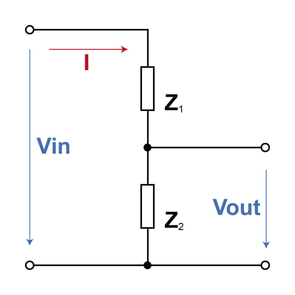
There are moments when you wish to reduce electric voltage by a certain constant factor. To achieve this, you simply add two resistors in sequence, here designated R1 and R2. The input voltage (Vin) is applied across the two resistors and the (lower) output voltage Vout emerges from the connection between them. The figure shows the corresponding circuit:

Function of the voltage divider
This type of voltage divider is also known as a potentiometer circuit, so we've got our first Eureka! moment right here:
A potentiometer must have something to do with a voltage divider.
But another important ingredient is missing in our voltage divider, since the values of Vin and Vout are fixed in our diagram. But a potentiometer comes with a knob or slide to change the values. So let's see how we should continue..
Step 3: application to controllable voltage dividers
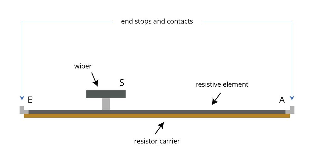
Sometimes you want to change the portions into which your voltage is divided. If so, you should manipulate one or, better yet, both of your resistors. In practice, what you do is equip the resistor with a third, moveable contact. This sliding contact, known as the wiper, divides the resistive element into two partial resistors. The sum of the two partial resistors is always identical to the entire resistor. The figure illustrates this principle:

Basic construction of a linear potentiometer
If the wiper is positioned in the middle, the resistors are identical. If the wiper is at quarter-position, one resistor comprises 25% of the total resistance, and the other 75%. Moving the wiper along the element thus causes a constant change in the relation between the resistors. Which brings us to our second Eureka! moment:
A potentiometer is a controllable voltage divider consisting of two resistors.
Due to its construction method, the potentiometer thus features a linear circuit of two changeable resistors with one constant toal value. Knowing, this, we now also know what a potentiometer actually is, a controllable voltage divider. But it can do more than that, for if you only connect the slider and one of the two end contacts, you get a controllable resistor. So you can always use a potentiometer when you wish to adjust a voltage or a resistance on a sliding scale


